

Rue des Sapins – ZI de la Castine
54730 GORCY – France
In the railway fields
Techno-Elec relays operation is based on the principle of electromechanical magnetic circuit. A flow is created in the magnetic circuit thanks to a current which goes through it, a permanent magnet creates an opposite flow which maintains the contacts in the rest position. As soon as the flow of the magnetic circuit overtakes the one of the permanent magnet, the relay triggers and closes.
The balancing of this armature and the use of a permanent magnet as a restoring means ensures rapid switching without any intermediate position. Mechanical principle of our contacts enable accurate settings. In order to design a voltage, current, differential or made-to-measure relay, Techno-Elec uses its magnetic circuits and standard boxes to compose relay blocks that can be adapted to most of the environments and electrical constraints, and this without additional external power supply.
Operation fields: from 1 mA to 15 000 A / from 10 mV to 4 000 V (AC/DC)
Dielectric strength: up to 20 000 V 50 Hz- 1 min (primary circuit/secondary circuit)
Auxiliary contacts usually 1 N/O 1 N/C, AgPd
High overloads on measuring circuit
Fire resistance according to standards NF F16-101-102 & EN 45545
Fully operationnal whatever is the direction
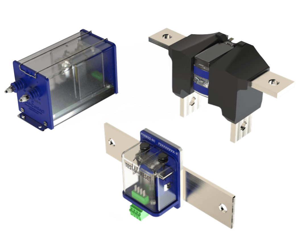
Protection relays are used in various applications within the railway industry, as well as in specific cases that require a customizable solution.
Explore use cases in railway systemsHigh galvanic separation
No auxiliary supply needed, stand alone
High reliability, no maintenance due to reliable and proven electromechanical technology
Strong ability to withstand high overloads
Equipped with weld no transfer
Contacts for critical applications
High speed response
Customizable to specific customer applications
IEC 60077 - Electrical equipment for rolling stock in railway applications
IEC 61373 - Shock & vibration - Railway application
NF F 16-101/102 - Fire and smoke behaviour for rolling stock
EN 45545 - Railway applications - Fire protection on railway vehicles
IEC 60068-2 - Environmental testing
EN 50124-1 - Railway Application Insulation coordination
EN 50163 - Supply voltages of traction systems
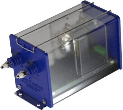
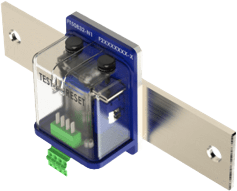
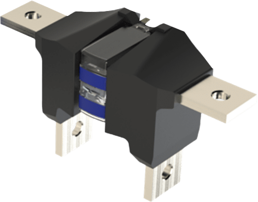
| Protection voltage relay | Protection current relay | Protection differential relay | |
|---|---|---|---|
 |
 |
 |
|
| Voltage measuring | From 10 mV – 4 000V (AC/DC) | – | – |
| Current measuring | – | 1A – 15 000A (AC/DC) | 1A – 15 000A (AC/DC) |
| Contact arrangement (1) | 1 N/O – 1 N/C | 1 N/O – 1 N/C | 1 N/O – 1 N/C |
| Accuracy | Up to 5% | Up to 5% | Up to 5% |
|
Dielectric strength (50Hz - 1min) • Between primary and secondary • Between each contact |
Up to 15 kV Up to 2.5 kV |
Up to 15 kV Up to 2.5 kV |
Up to 12 kV Up to 2.5 kV |
| Operating temperature | -40°C … +75°C | -40°C … +75°C | -40°C … +75°C |
| Terminals (2) | Faston (single, double), M4…M6, Push in connectors |
Busbar (for primary) Faston (single, double), M4…M6, Push in connectors |
Busbar (for primary) Faston (single, double), M4…M6, Push in connectors |
| Monitoring Functions |
Minimum voltage Maximum voltage Impulse voltage Differential voltage |
Minimum current Maximum current |
Differential current |
| More info | More info | More info |
| CONTACT | |
|---|---|
| Contact rating at 10⁶ operations | 137 Vdc : 0.3 A L/R = 30ms |
| Number of contacts |
Typically : 1 C/O | 2 C/O | 2 N/C | 1 N/O – 1 N/C | 1 N/O – 2 N/C Other configuration possible, please contact us |
| Contact resistance | < 20 mOhms (new). < 100 mOhms @ contact rating |
| Material | AgPd 70/30 |
| Contact safety | Weld no transfer |
| MECHANICAL CHARACTERISTICS | |
|---|---|
| Mechanical life | 108 operations |
| Contact life (mechanical) | 108 operations |
| Weight | Depends on relay. Typically between 0.5 and 1 kg. |
| ENVIRONMENTAL CHARACTERISTICS | |
|---|---|
| Environment testing | NF EN 60068-2 |
| Shock and vibration | NF EN 61373 |
| Operating temperature | -40°C...+75°C |
| Storing temperature | -40°C...+85°C |
| Protection degree IP | IP40 |
| Fire and smoke |
Other configuration possible NF EN 16-101/102 | EN45545 (R26-HL3) |